

Air Handling Units (AHU)
The complete range of SINKO air handling units can be configured in horizontal, vertical, suspended, or special ultra-slim designs to accommodate site space limitations, according to customer requirements. In addition to standard catalog models, custom-built units are available upon order.
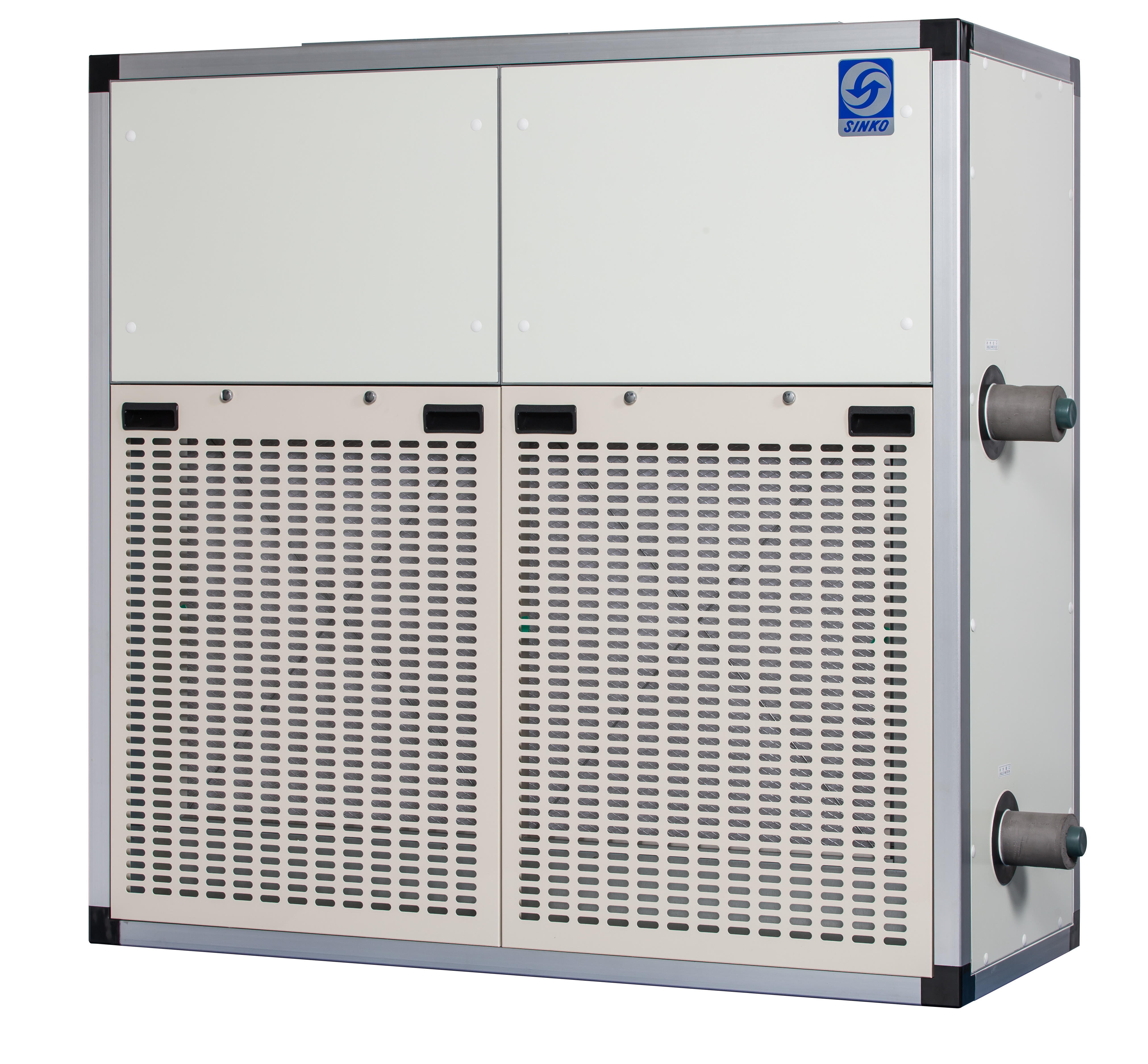
All units feature an aluminum alloy frame structure combined with double-skin panels injected with PU foam insulation. This construction provides complete thermal insulation inside and outside the unit, preventing condensation, ensuring excellent airtightness, offering high structural rigidity without deformation, low noise operation, and an aesthetically pleasing appearance.
In addition to general commercial applications (with special designs and manufacturing available upon request), these units are well suited for semiconductor-related facilities, department stores, commercial premises, hotels, hospitals, and various public spaces, offering a wide range of application options.
Product Features
Overview
Modular design with airflow capacities ranging from 2,500 CMH to 70,500 CMH.
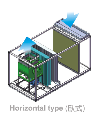
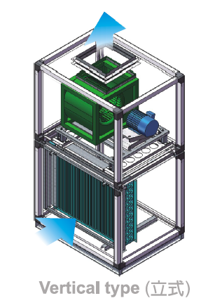
Three casing configurations available: horizontal, vertical, and suspended.
Entire product range designed, assembled, and manufactured in Taiwan.
Construction
Casing constructed with 30 mm or 50 mm thick double-skin panels.
Panels are available in painted steel, galvanized steel, or stainless steel, filled with 38 kg/m³ rigid PU (Polyurethane Foam) insulation.
Structural frame made of anti-condensation extruded aluminum profiles, effectively isolating thermal conduction between internal and external metal components.
Maintenance doors feature airtight, anti-condensation design and are equipped with ABS safety handles.
Built-in sloped SUS304 stainless steel drain pan.
Base frame fabricated from channel steel with anti-rust treatment for high strength and deformation resistance.
Coil Section
Coil liquid tubes available in copper with outer diameters of 5/8", 1/2", and 3/8".
Fin options include aluminum fins, corrosion-resistant aluminum fins, steel fins, and tin-plated copper fins.
Aluminum fin thickness: 0.12 mm to 0.30 mm
Corrosion-resistant aluminum fin thickness: 0.12 mm to 0.20 mm
Copper fin thickness: 0.12 mm to 0.20 mm
Coil end plates available in galvanized steel or stainless steel.
Headers made of galvanized steel pipes; stainless steel or copper pipes are available upon customer request.
Fan Section
Imported European and American centrifugal multi-blade fan assemblies, dynamically balanced.
All fan assemblies are equipped with independent spring vibration isolators to reduce vibration.
Forward-curved or backward-curved housed centrifugal fans can be selected based on system airflow, static pressure, and noise requirements.
Filter Section
Primary filters compliant with EN779:2002 G1, G2, G3, and G4 grades available.
Slide-out or spring-retained filter frames with excellent airtightness and easy removal.
Primary filters available in washable and non-washable types, with frame options including paper, aluminum, galvanized steel, and stainless steel.
Medium filters compliant with EN779:2002 F5 to F9 grades, using spring-retained frames for good airtightness and easy maintenance.
Final filters compliant with EN1822:1998 H10 to H14 grades, using screw-fixed frames to ensure superior airtightness.
Optional Accessories
Heating options: hot water coils, steam coils, or electric heaters.
Humidification options: high-pressure steam humidifiers, electric pan humidifiers, electrode humidifiers, or ultrasonic humidifiers.
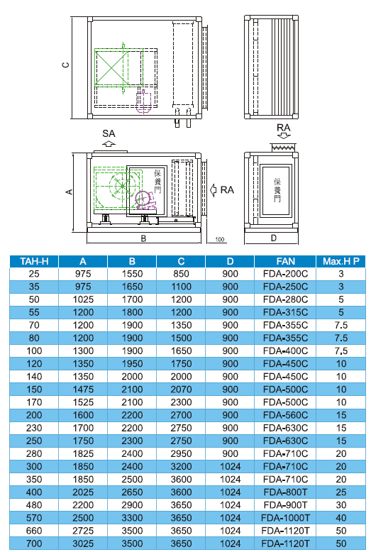
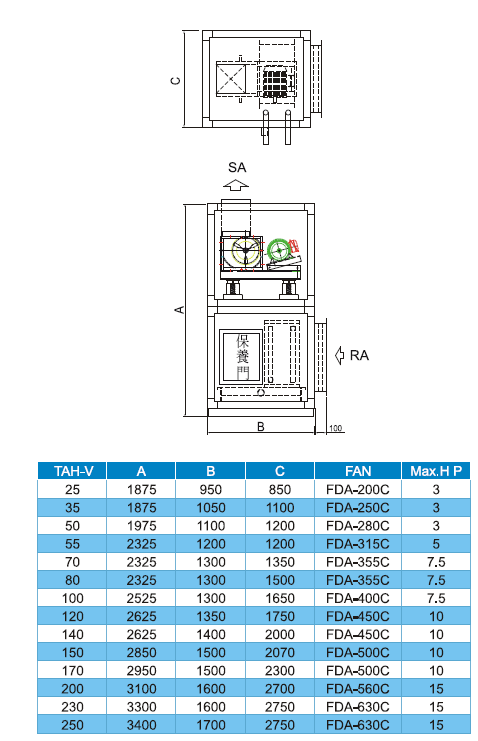
Product Specifications
Horizontal type
Vertical type
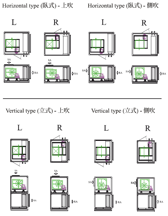
Fan Orientation / Chilled Water Piping / Maintenance Door Selection
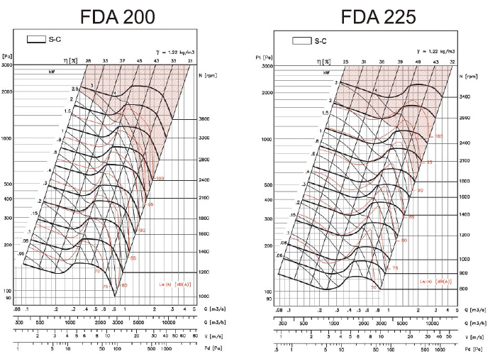
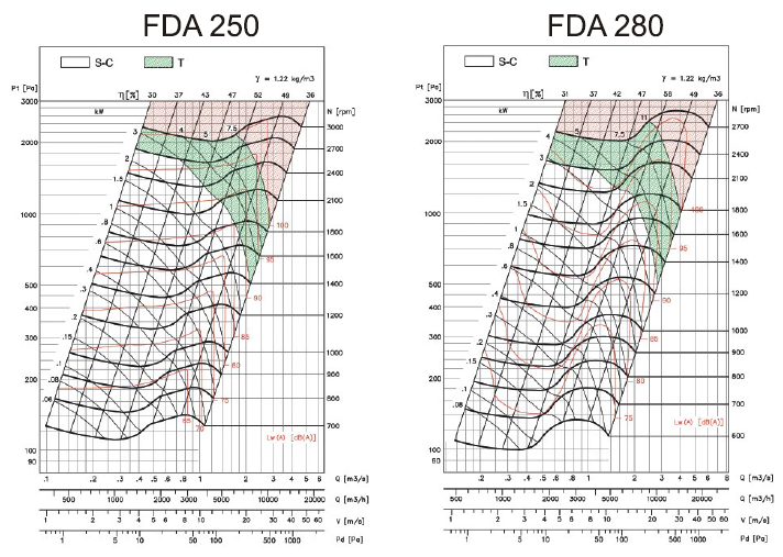
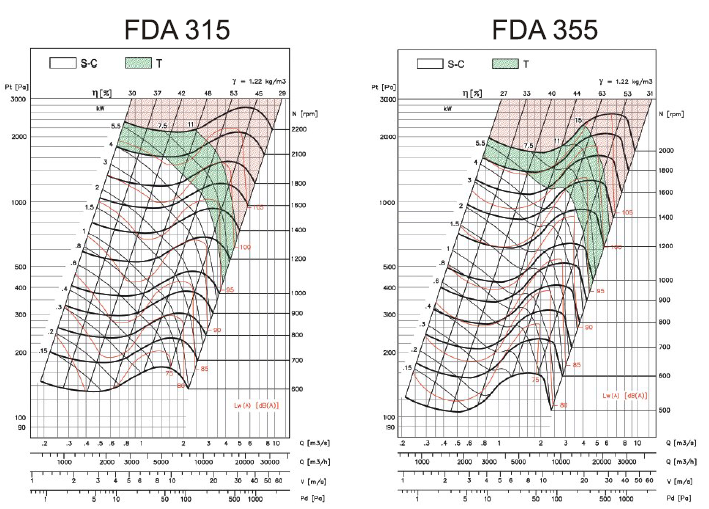
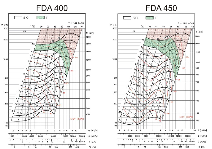
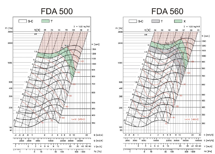
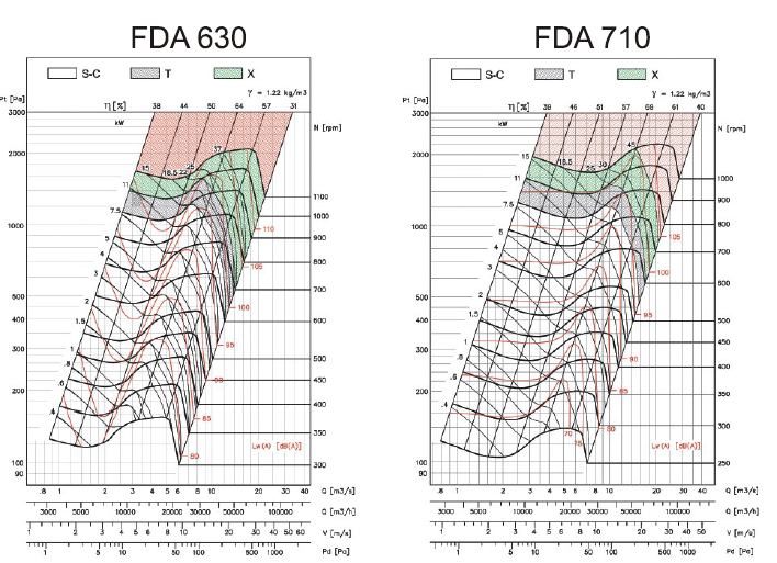
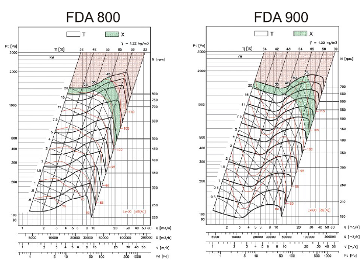
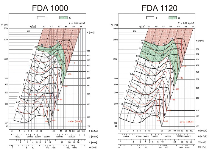
Fan Performance Curve
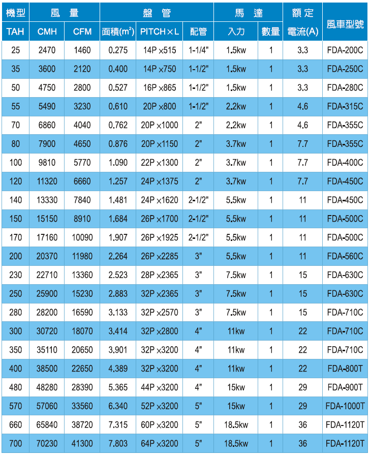
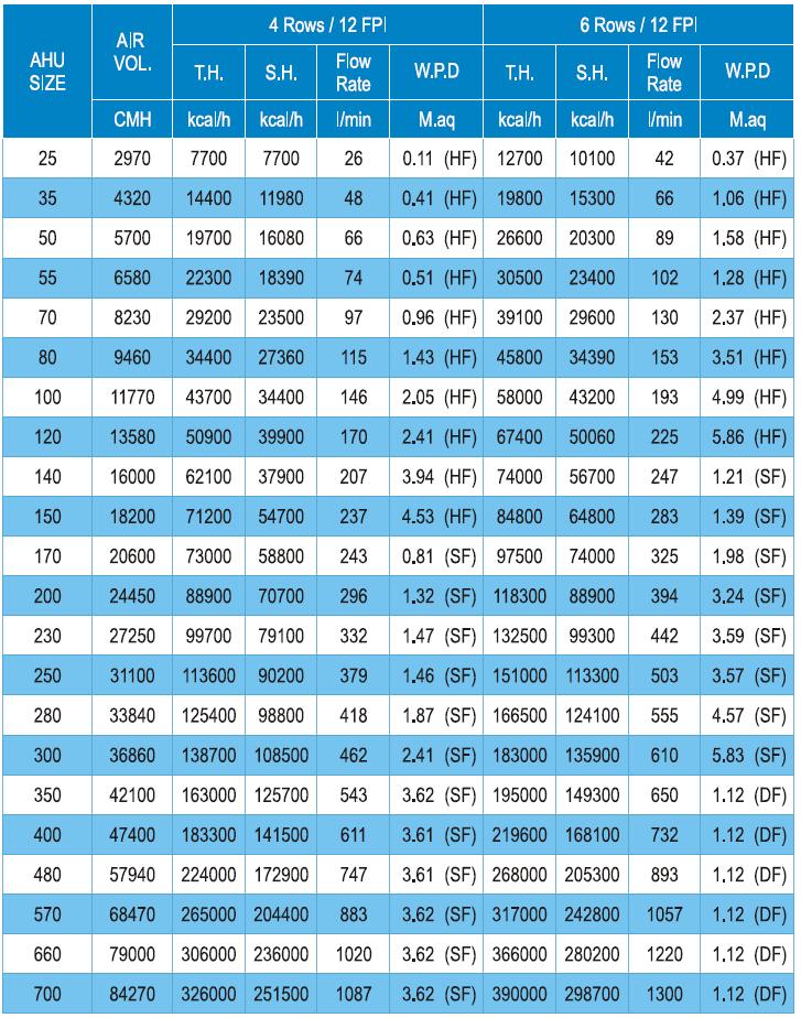
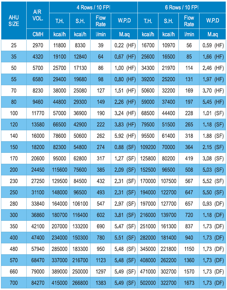
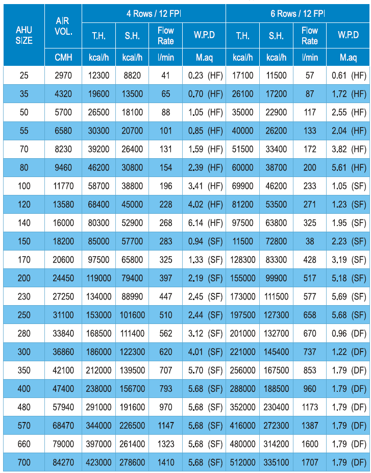
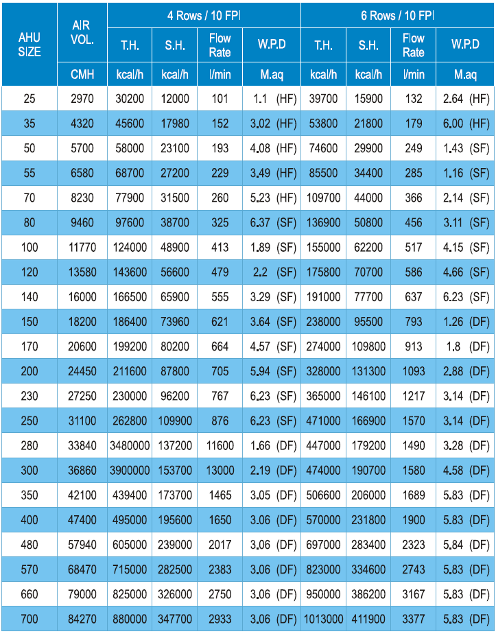
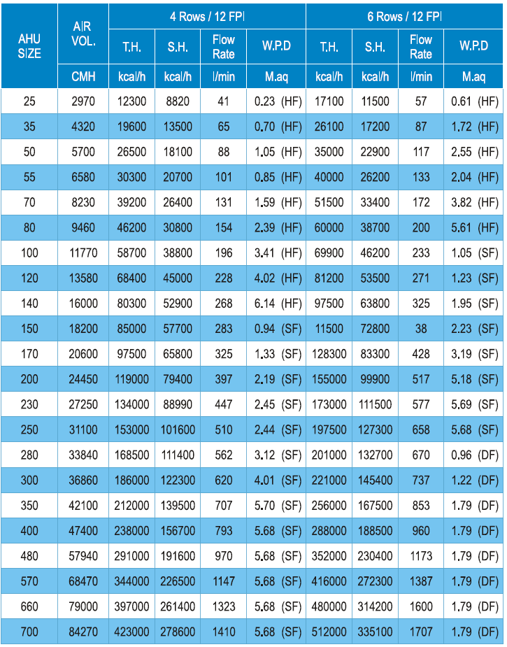
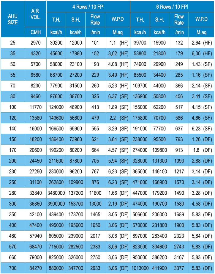
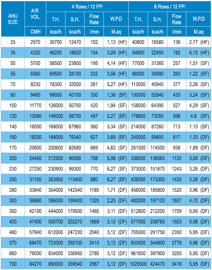
Specification Table
Face air velocity: 2.5 m/s
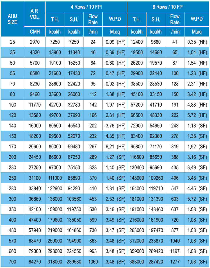
Cooling Capacity
Air Dry-Bulb Temperature: 24 °C
Chilled Water Outlet Temperature: 7 °C
Air Wet-Bulb Temperature: 17 °C
Chilled Water Inlet Temperature: 12 °C
Face air velocity: 3.0 m/s
Air Dry-Bulb Temperature: 24 °C
Chilled Water Outlet Temperature: 7 °C
Air Wet-Bulb Temperature: 17 °C
Chilled Water Inlet Temperature: 12 °C
Face air velocity: 3.0 m/s
Face Velocity vs. Airflow Reference Table
Air Dry-Bulb Temperature: 26 °C
Chilled Water Outlet Temperature: 7 °C
Air Wet-Bulb Temperature: 19 °C
Chilled Water Inlet Temperature: 12 °C
Face air velocity: 3.0 m/s
Air Dry-Bulb Temperature: 26 °C
Chilled Water Outlet Temperature: 7 °C
Air Wet-Bulb Temperature: 19 °C
Chilled Water Inlet Temperature: 12 °C
Face air velocity: 3.0 m/s
Air Dry-Bulb Temperature: 35 °C
Chilled Water Outlet Temperature: 7 °C
Air Wet-Bulb Temperature: 28 °C
Chilled Water Inlet Temperature: 12 °C
Face air velocity: 3.0 m/s
Air Dry-Bulb Temperature: 35 °C
Chilled Water Outlet Temperature: 7 °C
Air Wet-Bulb Temperature: 28 °C
Chilled Water Inlet Temperature: 12 °C
Face air velocity: 3.0 m/s
Installation and Maintenance Precautions
Handling
During transportation, care must be taken to protect the air handling unit casing. When lifting or moving the unit, it must be kept level and not excessively tilted to prevent damage to the casing structure or displacement of internal components. After transportation is completed, the casing and all internal components must be inspected for any displacement or damage.
Casing
When installing individual casing sections, ensure that all sections are tightly fitted together. After positioning, all connections must be accurately aligned.
Use bolts with nuts to secure the connections and ensure proper sealing between casing sections. Deformation or separation must be avoided, as this may result in poor airtightness.
The casing must be installed in a level position and must not be inclined. Otherwise, improper drainage of the drain pan may occur, leading to water leakage, or imbalance of the bearings and fan may result in abnormal vibration due to loss of dynamic balance.
Piping Work
The air handling unit must be installed on vibration isolators. Additional vibration isolation measures should be applied as required by the operating conditions.
Drainage Piping and U-Trap Installation Notes:
The drain pipe must be installed with a U-trap, as shown in Figure (1). The height of the water seal must be greater than the internal static pressure of the unit to prevent improper drainage. The drain pipe must maintain a sufficient slope to ensure smooth drainage and to prevent water accumulation inside the casing.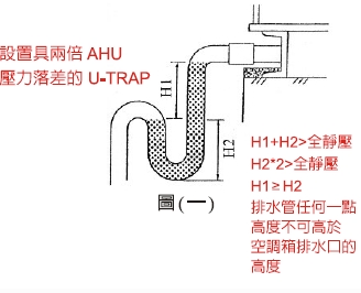
Install the drain line drain valve and connect it to the floor drain.
Verify the dimensions of the duct inlet/outlet and flange connections.
A flexible canvas connector with good elasticity must be installed between the air outlet and the ductwork to isolate vibration.
After installation of the air handling unit is completed, inspect all internal components to ensure proper installation. Remove any temporary fan fixing devices and adjust the vibration isolation springs to their correct positions.
During equipment installation, ensure proper intake of outdoor air and smooth return airflow to prevent noise generation.
Ductwork installation should be designed to maintain smooth airflow and minimize system effect losses.
Start-Up
Before start-up, confirm that the power supply voltage is correct.
Check motor input power and cooling capacity.
Inspect airflow rate, water temperature, and water flow rate.
Observe the unit during start-up for any abnormal noise. If abnormal noise is detected, stop the unit immediately and perform an inspection.
Verify that temperature, humidity, and air pressure sensors are operating correctly.
Maintenance and Service Clearance
Regularly inspect the operating condition of the air handling unit and clean the filters on a scheduled basis.
To prevent freezing caused by residual water inside the coils, completely drain all remaining water from the coils when the unit is not in operation.
The installation location of the air handling unit must fully consider noise and vibration control and provide sufficient maintenance clearance. A minimum clearance of approximately 600 mm is required.
This space is necessary for installing U-traps, servicing fan bearings and motors, and for maintenance tasks such as removing and replacing filters, coils, and electric heaters, as well as cleaning coils and filters.